2021 Toyota Highlander Installation
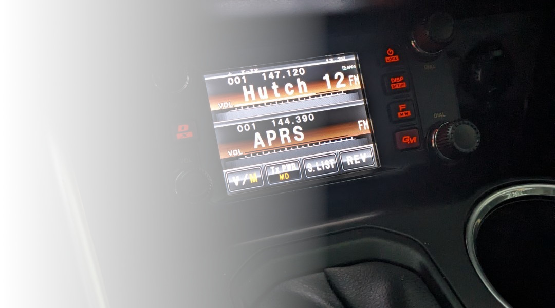
Each time I trade vehicles, I try to improve upon the quality of my ham radio installation. After a bird-incident with a hood-mounted antenna a few years ago, I now try for a rear-mounted VHF/UHF antenna. The compound curves and multitude of plastic parts on the back of the 2021 Toyota Highlander made this installation a little tricker than those in the past, but I'm very happy with the results.
I started this installation by planning the power wire penetrations through the firewall. For this vehicle, I went a little bit of a different route than I've taken in the past by actually traversing the wheel well to get inside of the cab. The Highlander is pretty cramped along the firewall in front of the driver, so this was the easiest path.
Start by spooling off a sufficient length of quality power wire from the battery, rearward towards the front of the drivers side fender.
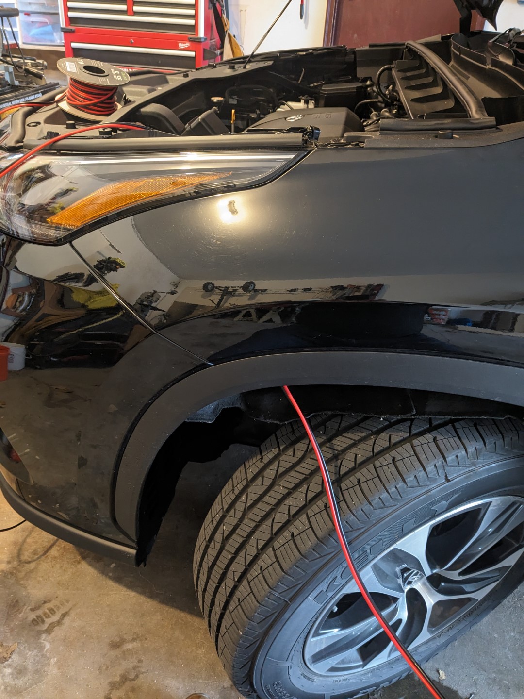
The protective cover on the wheel well comes apart with just a couple of screws and latches. You only need to get to the top part of the well, so a full removal isn't necessary. Turning the steering wheel to the left helped the access towards the rear.
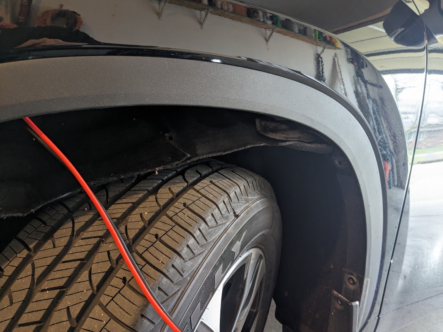
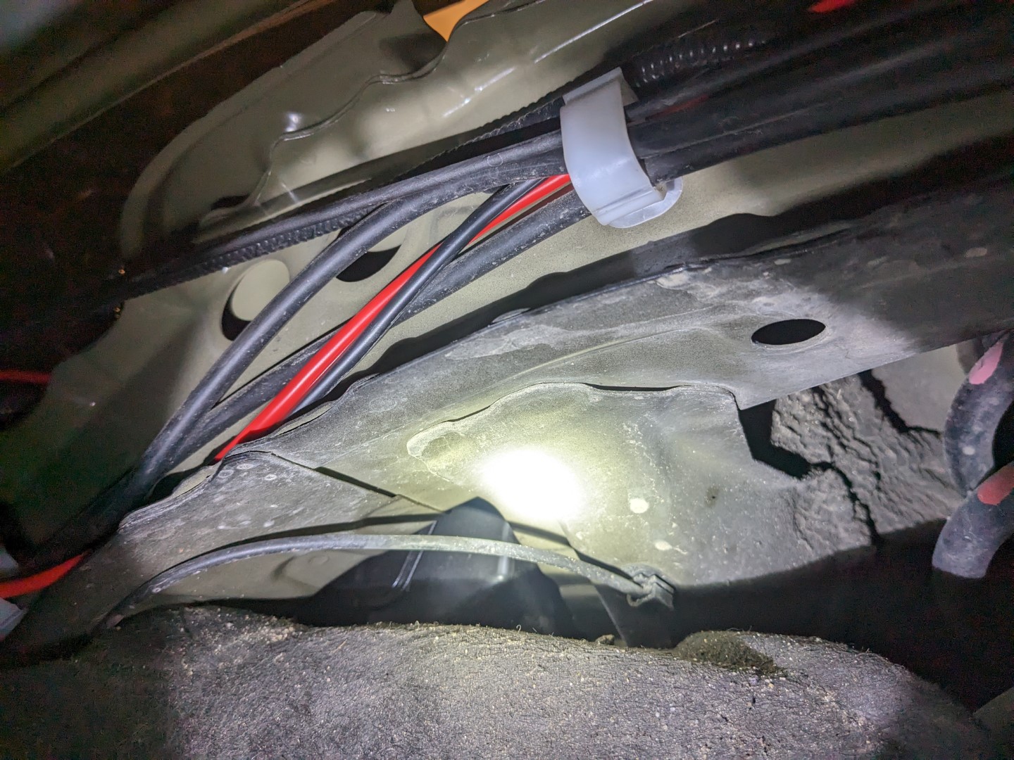
Once you're into the wheel well, there are several other cables that you can follow the path with.
Towards the rear of the well, you'll find a thick jacketed cable for the hood release. That's where I actually went through the firewall. Double check yourself that you're actually looking at that hood release cable (a physical cable, not an electrical cable) and use an Xacto knife to cut a small slit in the rubber feed through. You should be able to push the radio power cable through that slit into the passenger compartment.
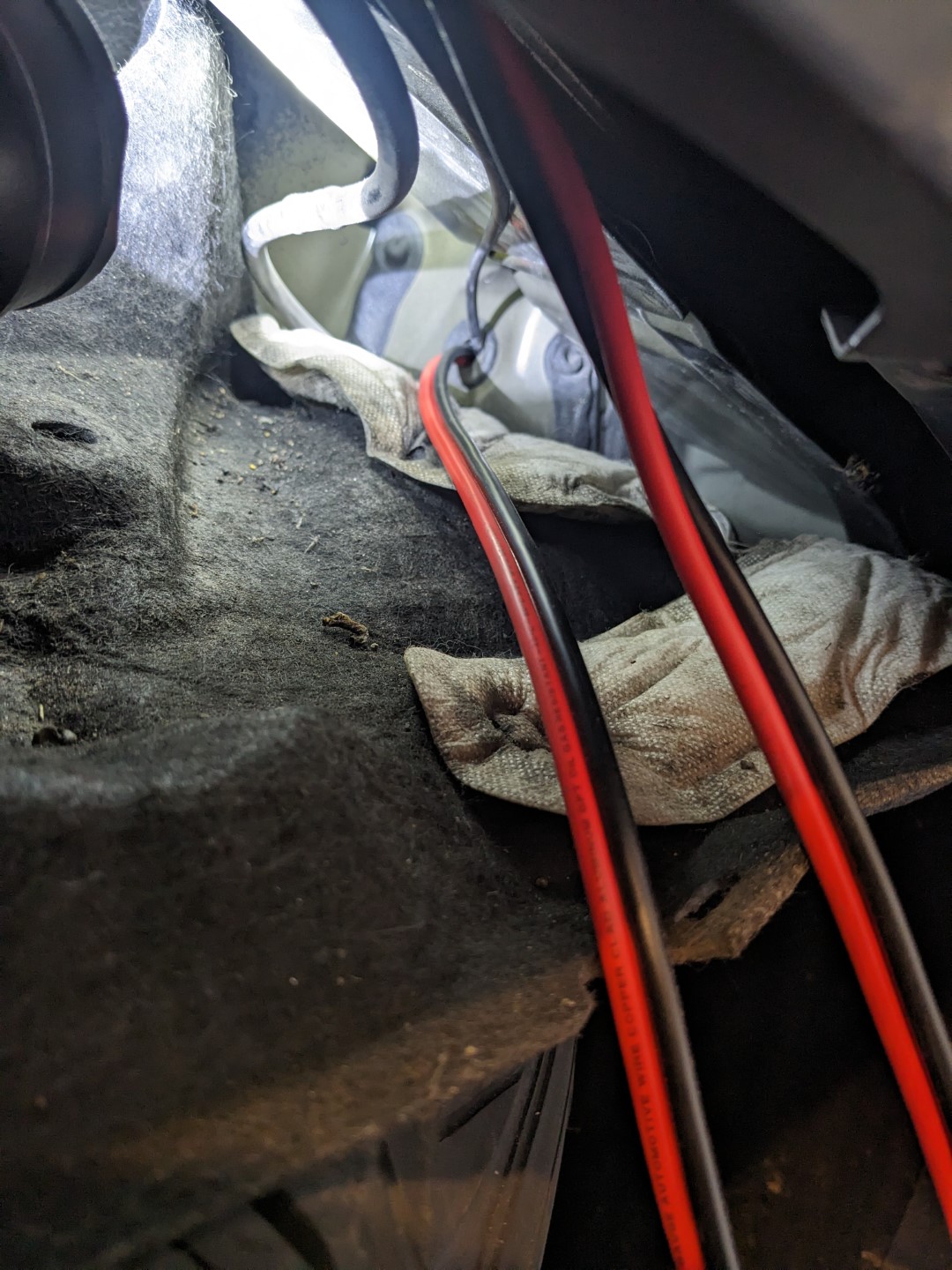
Tidy up the cabling inside of the wheel well by using the existing cable clamps that run along the top side of the well.
Once you're in the passenger compartment, you will need to remove several pieces of plastic trim along the driver side outside door. I believe all of these came out without the use of tools. Just becareful not to break any of the retaining clips.
Route the power power along the outside wall down and parallel the existing cable bundle that runs towards the rear of the vehicle.
I went to the rear side of the front door and then turned inward to end up under the drivers side car seat.
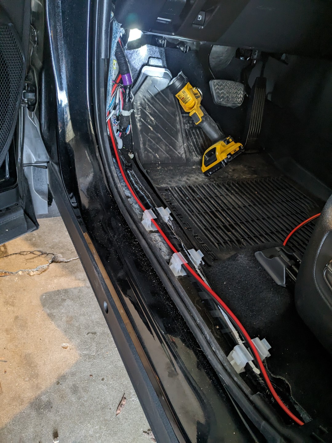
Once you're in the passenger compartment, you will need to remove several pieces of plastic trim along the driver side outside door. I believe all of these came out without the use of tools. Just be careful not to break any of the retaining clips.
Route the power wire along the outside wall down and parallel the existing cable bundle that runs towards the rear of the vehicle.
I went to the rear side of the front door and then turned inward to end up under the driver's side car seat.
To mount the antenna, I fabricated a small bracket that I cut from 19ga (0.0438") sheet steel, although I would step up one thickness if I were to do it again. The pattern is in the downloads above, and can be printed and transferred onto the sheet steel using a marker or scribe. I had a pair of electric sheet metal sheers which made cutting the pattern out very easy, but the same could be accomplished with an angle grinder. No matter what you use, be sure to use appropriate eye protection.
The pattern will need three holes drilled for the antenna and the two mounting bolts, and then a pair of 90 degree bends applied along the dotted lines.
I carefully applied a small bead with a MIG welder on the inside corners of the 90 degree bends to add rigidity, although that's probably not necessary especially if you used a thicker gauge steel than my 19ga. Once the bracket is drilled and bent, clean the metal thoroughly with sand paper and file all of the edges so they aren't sharp.
I prepared the surface with a rag and some acetone. After allowing it to dry, I applied two coats of a quality metal primer from a spray bottle. I let that dry and finished it up with a couple of coats of an enamel spray paint.
Let the part cure for 24-48 hours before moving forward with reassembly.
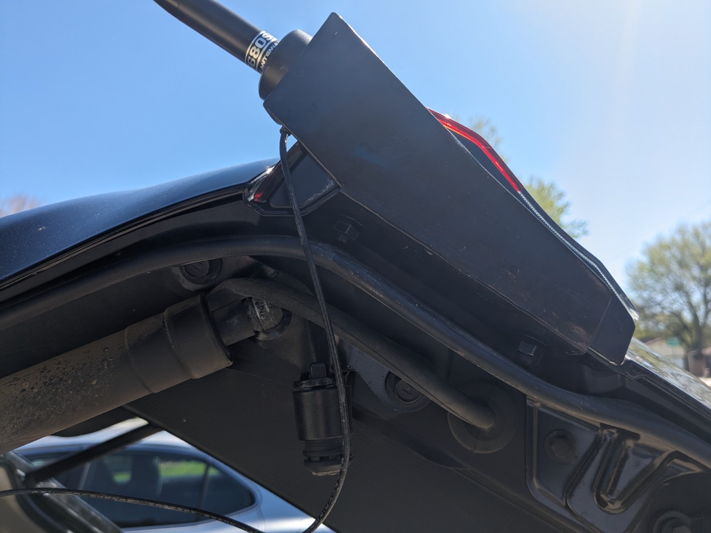
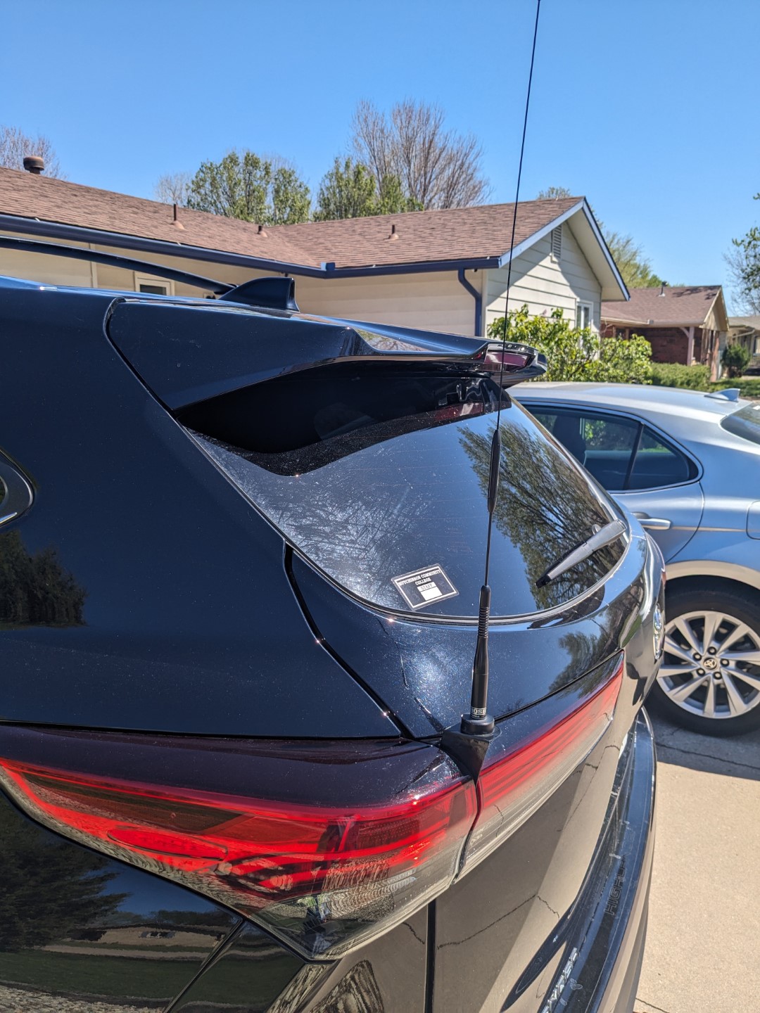
On the rear of the vehicle, open the hatch. There are two bolts inside of the door frame that hold the taillight in place. Remove those two bolts and pull straight back on the driver side taillight to expose two rubber plugs that pass from the taillight into the space that the above-mentioned access panel goes to.
Remove one of the rubber plugs. Depending on the coax and connectors you're using, you may need to enlarge the hole with a drill.
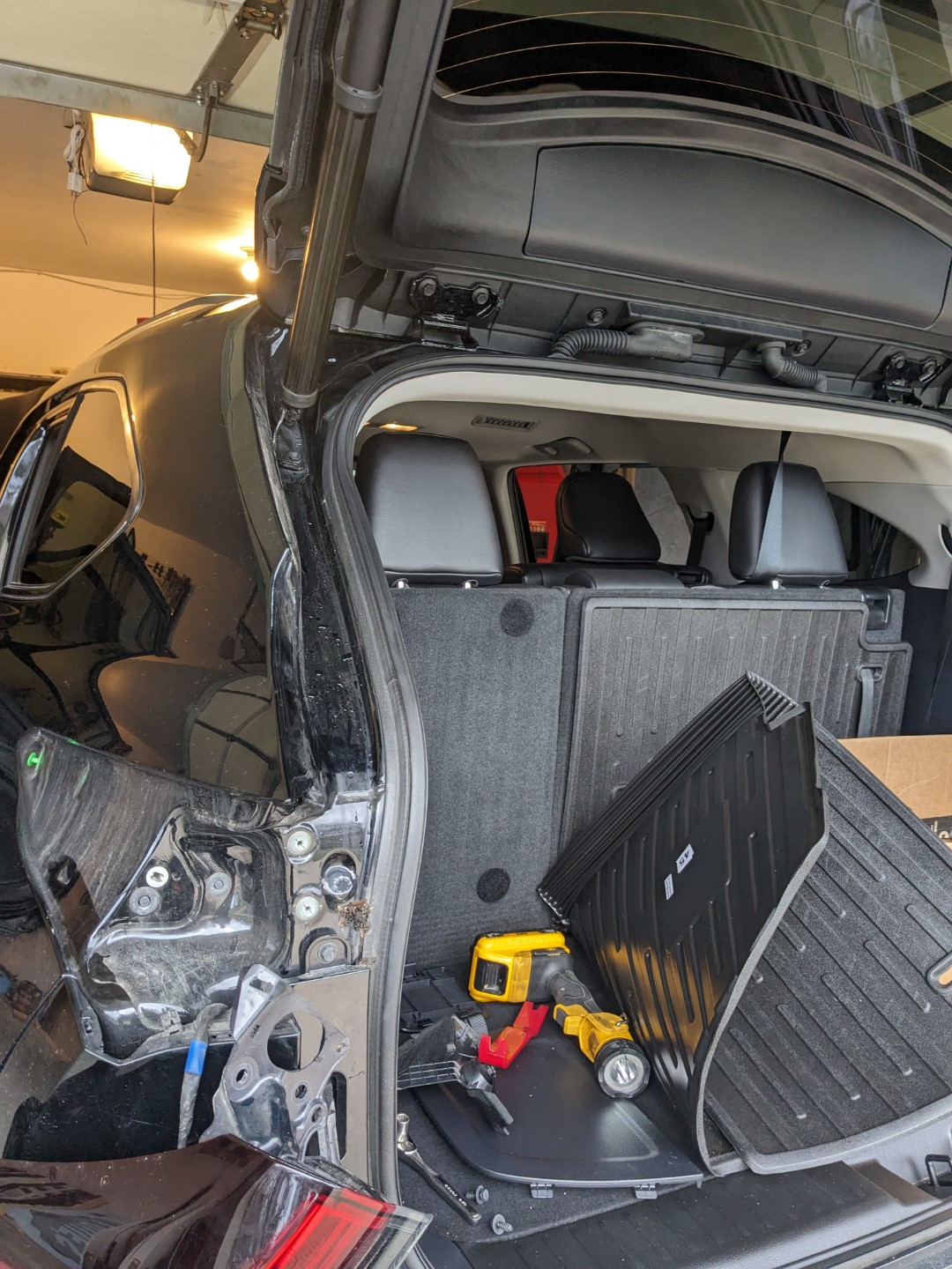
Pass the 1/8" Teflon coax through the enlarged hole and into the interior of the vehicle. At this point, attach the Diamond C110 extension cable to the small feeder coax.
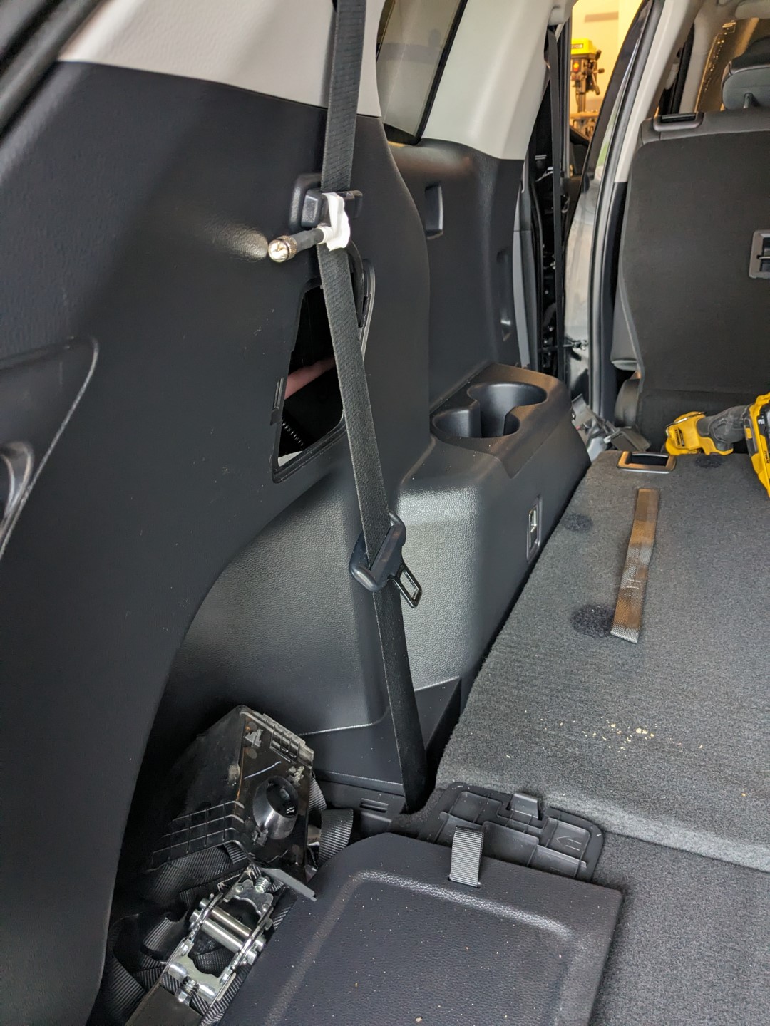
You can now begin the reassembly of the taillight and the access panel door.
Reattach the plastic molding pieces along the bottoms of the door frame, and tuck the coax and power cables up out of the way.
Back at the front, I mounted the Yaesu FTM-400 radio to the carpet under the drivers seat by simply applying the rough side of some stick-on Velcro material to aluminum angle that I screwed to the radio. That keeps the radio separated from the floor by just a few millimeters which helps with cooling.
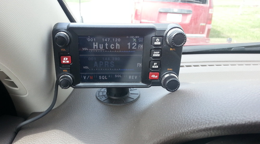
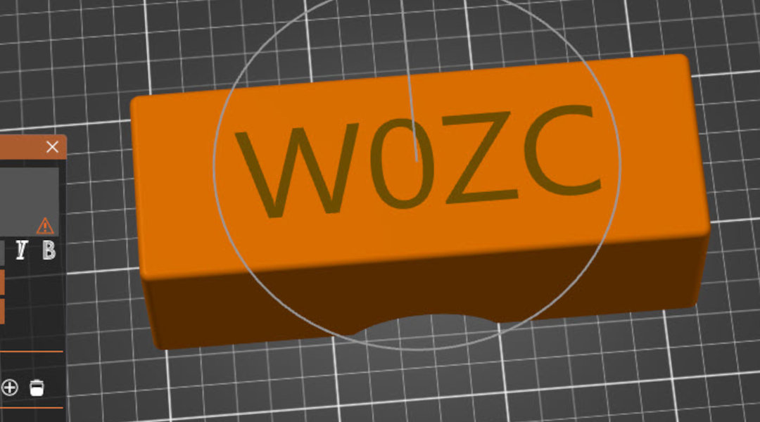
I 3D printed a bracket that slips into the cubby hole next to the USB power outlets on the front console. The bracket has a single hole in it for a bolt which can be used to attach the front face of the radio. Be careful not to use too long of a screw that could damage the interior of the head unit if it is over-tightened.
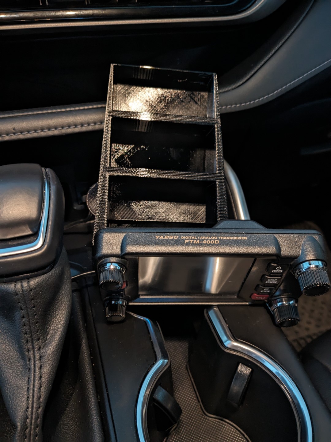
The small ribbon wire exits the back of the head unit and got to the left. I considered pulling the middle console and running the wire down near the shifter, but for now I managed to squeeze the wire between the plastic pieces of the console, and then go down the left side of the console near the driver's feet. I route it back towards the seat and cable-tie it together with Vehicle Power Management system.
I mounted the microphone holder bracket to the console by using a pair of very short sheet metal screws. When drilling the plastic of the console, be very careful with the drill as there are likely wires behind the plastic that could be damaged.
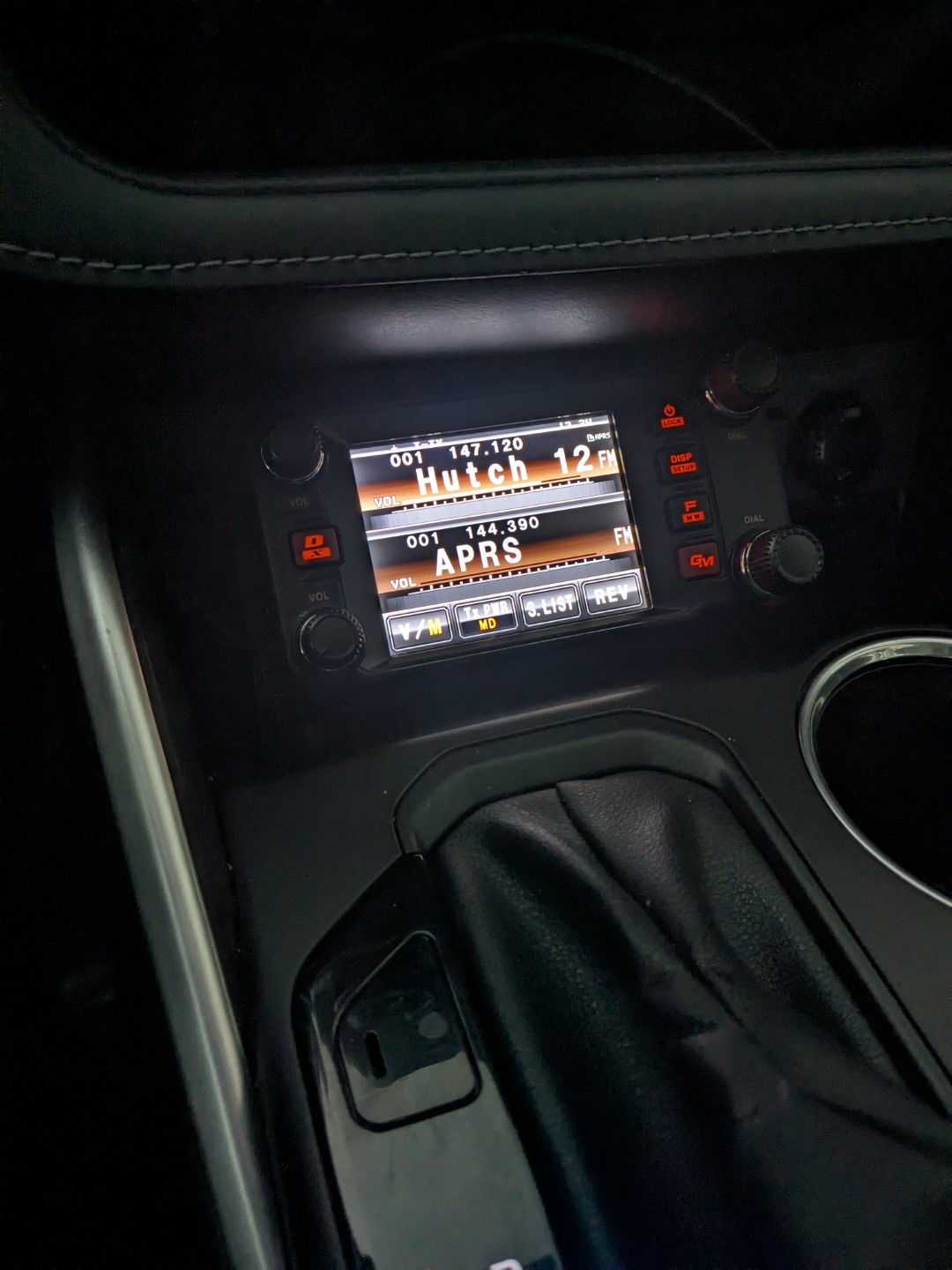
Parts List
Diamond C110 Coax Cable
Diamond C101NMO Mount
Comet SS-680SBNMO Antenna
20' 12ga Power Cord
Fuse Holder w/ 25A fuse
Crimp Terminals (for battery)
Power Pole Connectors
Related Articles


