Portable 40m Vertical
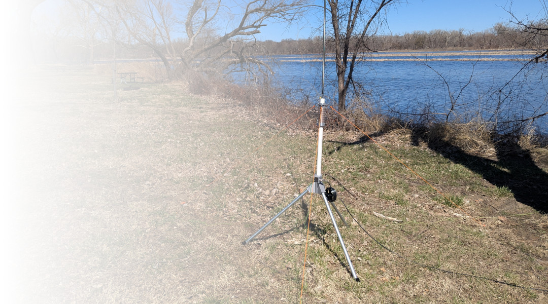
While I really like my end-fed dipole for POTA activations, I was looking for something that might be self supporting for quicker deployments and to be less intrusive. I briefly considered a few other mast-supported options but eventually landed on a shortened vertical for its simplicity and efficiency.
I started this design with 17 foot telescoping width from MFJ. The 17 foot whip is conveniently sized to operate as 1/4 wavelength 20m vertical antenna and I used this for about a year with a simple C-Clamp mounting bracket. As I began to plan for an upcoming trip, I decided that 40 meters would be a requirement for this particular outing. A 40m quarter wave full size vertical would be over 30 feet tall which is not practical for a portable installation.
Assembly
I began working on the physical construction of the antenna along with the required feed point to attach my coax to. The resulting antenna can be built to any length from about two feet up to over 8 feet in height. There are a couple of practical limitations to the choice as it becomes difficult to extend the telescoping whip if the base of the antenna is much taller then about chest height. Alternatively, the efficiency of the antenna drops off as the loading coil gets closer to the feed point, so a compromise must be weighed. It also should be noted that the optional tripod base adds some height to the bottom of the antenna and needs to be considered.
The design that I'm showing here is a portable and antenna that can be packed inside of a large suitcase with the loading coil section of the antenna roughly the same length as the telescoping width. I have experimented with other sizes and use longer antennas for some applications where size isn't the constraining factor.
Bill of Materials
In the resources section above I have included links to the STL files where you can download the coil forms. You will need to determine which size of PVC pipe you wish to use, and print the appropriately sized files. I’ve done extensive testing with PETG material in high temperatures and in UV exposure, and have found that it is adequate for at least medium lengths of time in the outdoors. When printing, I've had good luck printing it at 25% infill, as several of the connection points are compression-based, and the extra infill handles that load.
In addition to the printed parts, you will need the following items from the Bill of Materials.
Qty | Description | Source | Notes |
|---|---|---|---|
1 | 17' Telescoping Whip | DX Engineering, Gigaparts, HRO | CHA-SS17 or MFJ-1979 |
2-8' | PVC Pipe (1.25, 1.50, or 1.75") | Local Hardare Store | |
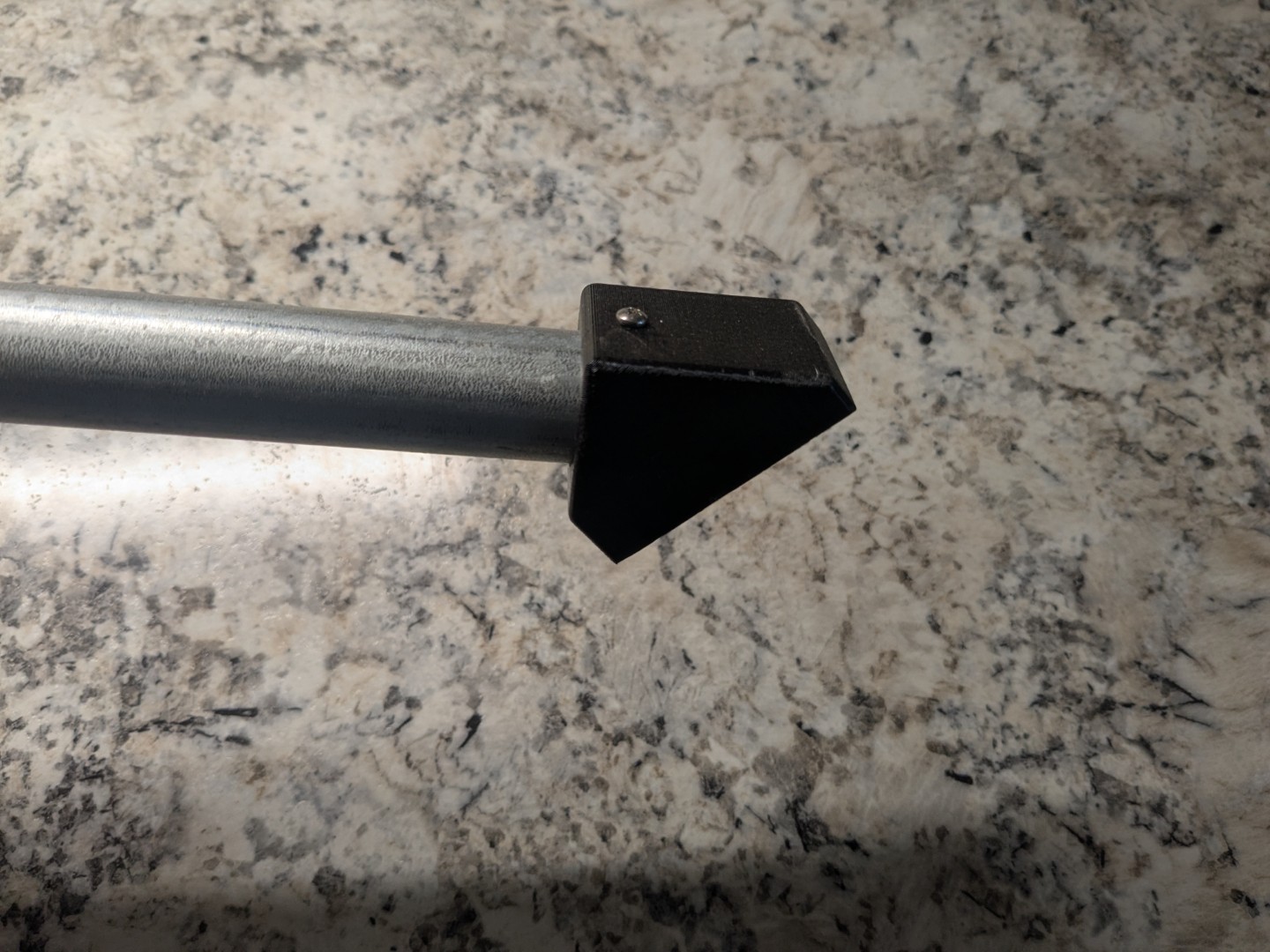
1 | PVC End-cap | Local Hardware Store | Optional if you're not using the tripod to keep the PVC from sinking into the mud. |
1 | 3/8" Crimp Terminal | Local Hardware Store | |
1 | #4 Crimp Terminal | Local Hardware Store | |
3 | #10 Crimp Terminal | Local Hardware Store | |
25' | 12ga bare copper wire | Local Hardware Store | Can be stripped from 12-2 house wiring. |
2' | 14ga silicon test lead wire | Digikey | 1175-3644-16-1-0500-001-1-TS-DS-ND |
1 | Small alligator clip | Digikey | 314-1011-ND |
4 | Large alligator clips | Digikey | 314-1033-ND |
1 | 3/8-24 "fine thread" coupler | Local Hardware Store | |
2 | 3/8-24 "fine thread" nuts | Local Hardware Store | |
1 | 3/8-24 "fine thread" bolt - 3" long | Local Hardware Store | |
20' | Lightweight rope | Local Hardware Store | For the guy lines |
3 | Tent Stakes | Local Hardware Store | |
3 | #10 x 2.5" bolts | Local Hardware Store | 10-24 or 10-32 are fine, but be consistent |
1 | #10 x 3" bolt | Local Hardware Store | |
12 | #8 flat washers | Local Hardware Store | The #8 washer should tightly fit around a #10 bolt, but verify. |
4 | #10 nuts | Local Hardware Store | Verify same thread as the bolts from above. |
4 | 4-40 x .75" bolts | Local Hardware Store | |
4 | 4-40 flat washers | Local Hardware Store | |
4 | 4-40 nuts | Local Hardware Store | |
1 | SO-239 chassis mount | Digikey | 182341 |
8' | 3/4" electrical conduit | Local Hardware Store | Optional legs for tripod |
10 | #4 machine screws | Local Hardware Store | |
150' | 18ga (or finer) wire for radials | Local Hardware Store | 150' will yeild four 40m radials. Four should be considered minimum. |
Assembling the Top End
The first step to assembly is to determine the overall length of the PCB base. You can certainly dry-fit a few of the elements together to try various lengths, but it becomes increasingly difficult to cut the pipe down once assembly is fully underway. If you plan on using this portable, I'd recommend 4', give or take 1 foot depending on how tall you are.
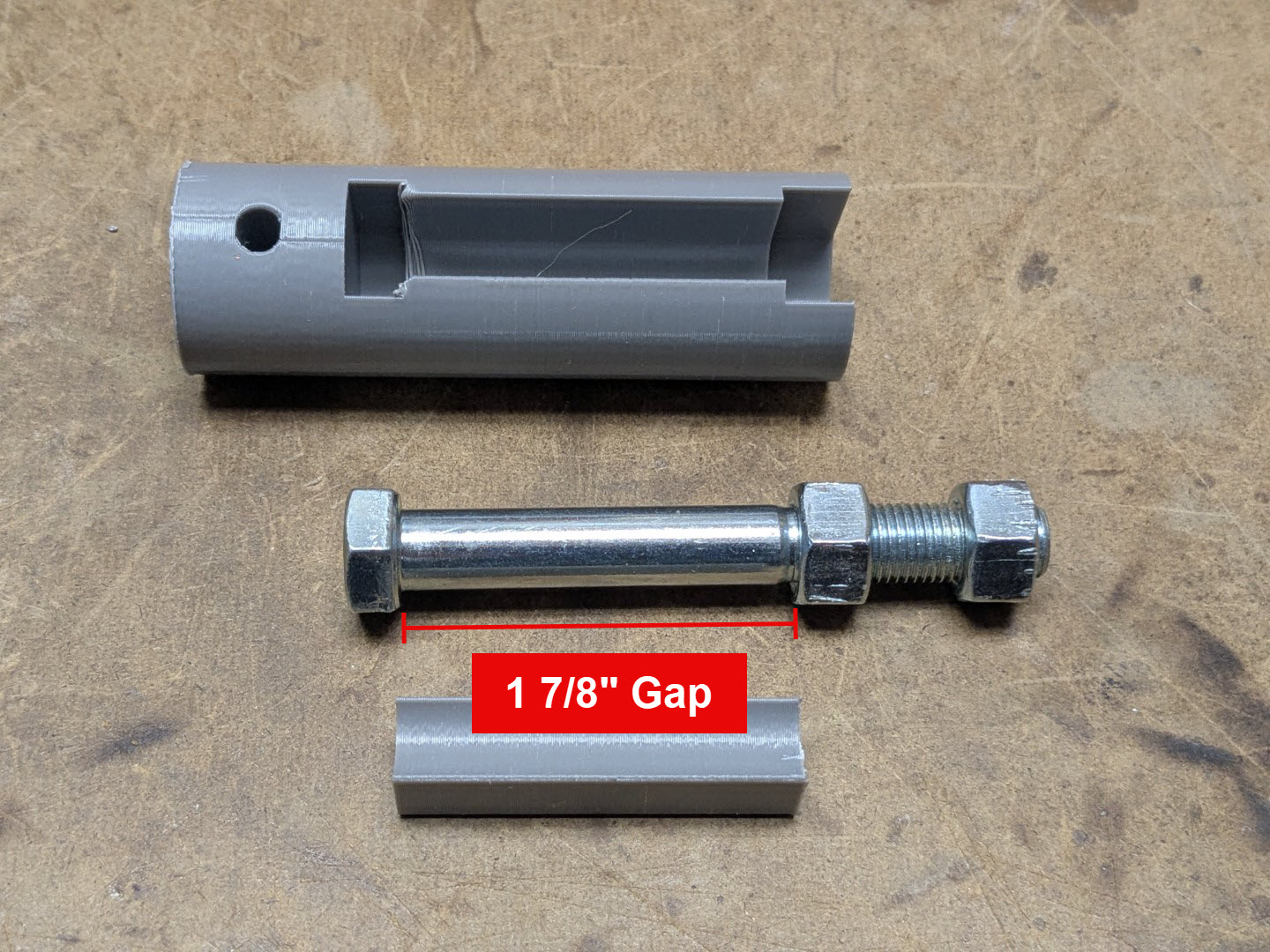
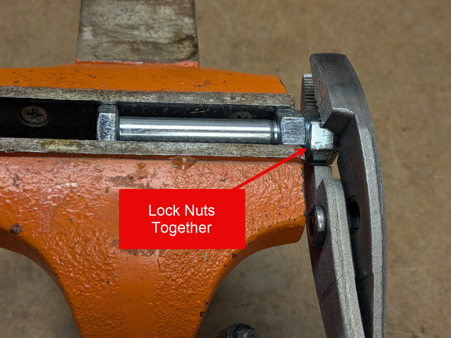
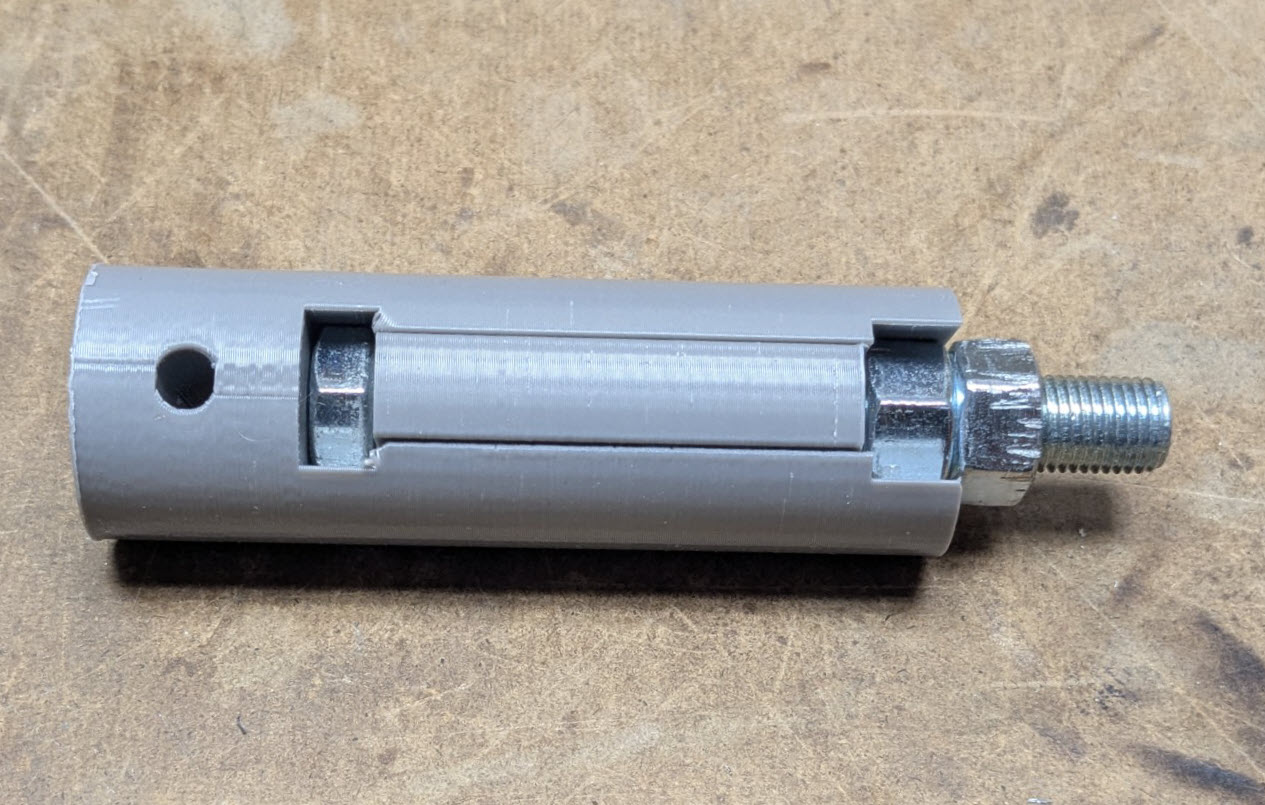
Begin by installing the 3 inch, 3/8" bolt into the carrier. Using the printed carrier as a guide, thread the nut down the bolt, leaving about a 1-7/8" gap between them. Align the head of the bolt with the nut, and clamp it into a vice. It is important that the faces of the nut and bolt head remain parallel during this step.
Using a second nut, threat it onto the top of the bolt, and lock it tightly against the first nut to secure its position. Optionally, you can also tack a small weld on the back side of the first nut to further secure it in position.
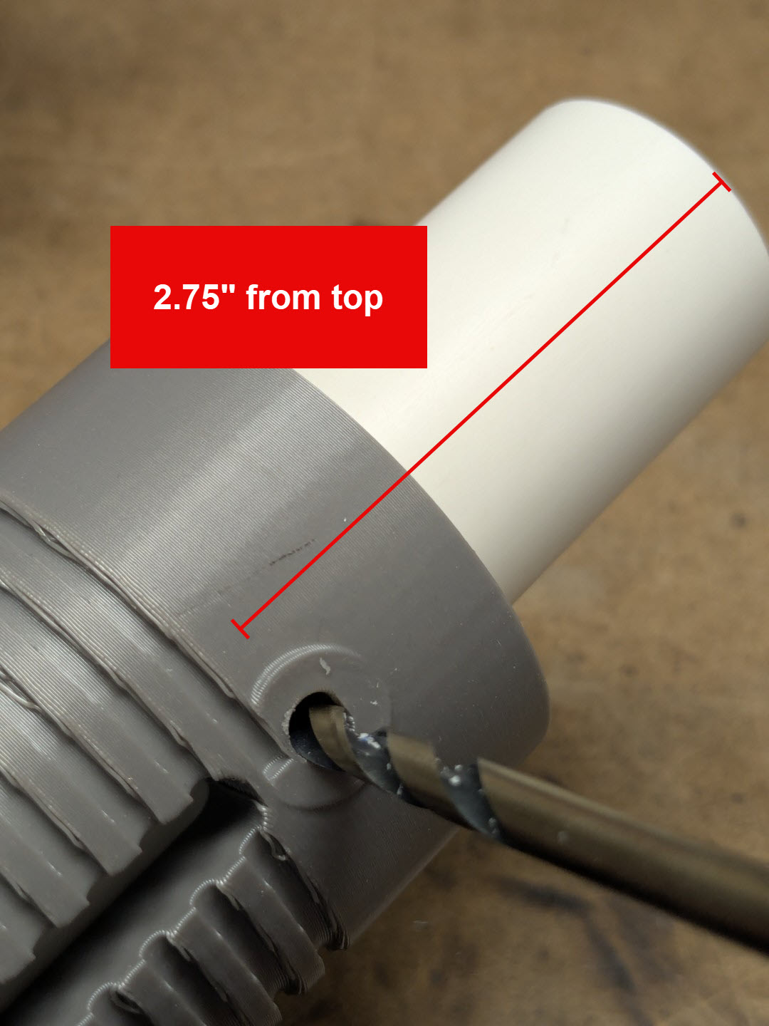
Measure down 2.75" from the top end of the PCV pipe and drill a single 3/16" hole into the side of the pipe. Slip the coil form down over the pipe and insert a 2.5" #10 bolt into the hole, fixing the form in place.
While this is being held and using the coil form as a guide, drill the second hole into the opposite side of the coil form.
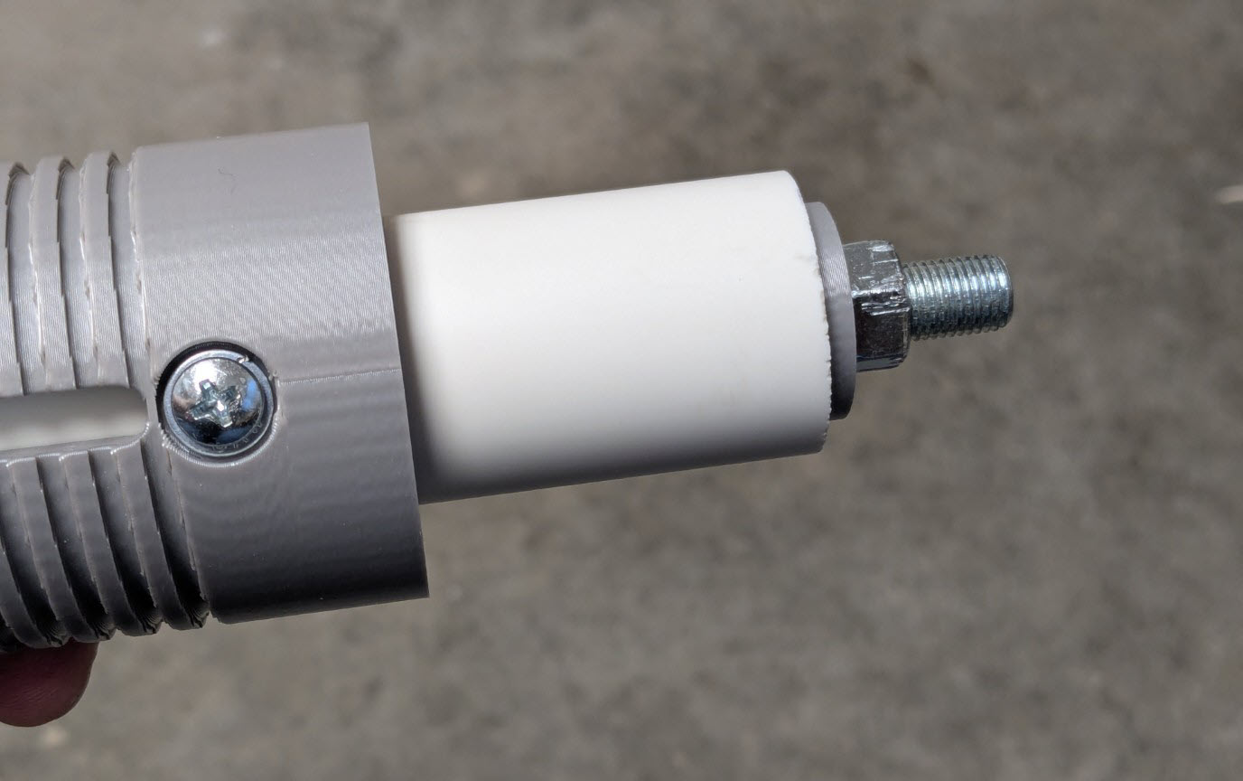
Insert the 3/8" bolt into carrier, and lock it in place with the carrier insert.
Slide the carrier into the top of the PVC and align with hole that you just drilled. Align top hole in the coil form. Using a #8 washer and a 2.5" long #10 bolt, insert the head of the washer into the side of the coil form that has an inset screw head.
Loosely attach a second #8 washer and a nut onto the opposite side of the coil form.
Using the 3/16" drill bit, drill both sides of the bottom hole in the coil form. Use the coil form as a guide, and just drill through the PVC half way.
Use a #8 washer and a 2.5" #10 bolt to secure the bottom of the coil form, just like the top side. Loosely attach at #8 washer and nut to the second bolt.
Winding the Coil
You will need 15' of bare 12 gauge copper wire. I used some old Romex 12-2 house wiring that I had laying around. Starting at one end, bend the tip of the wire into a small loop, just big enough to fit around the #10 bolt at the bottom of the coil form.
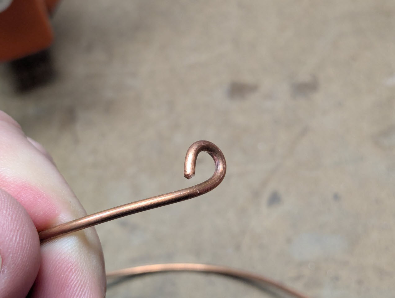
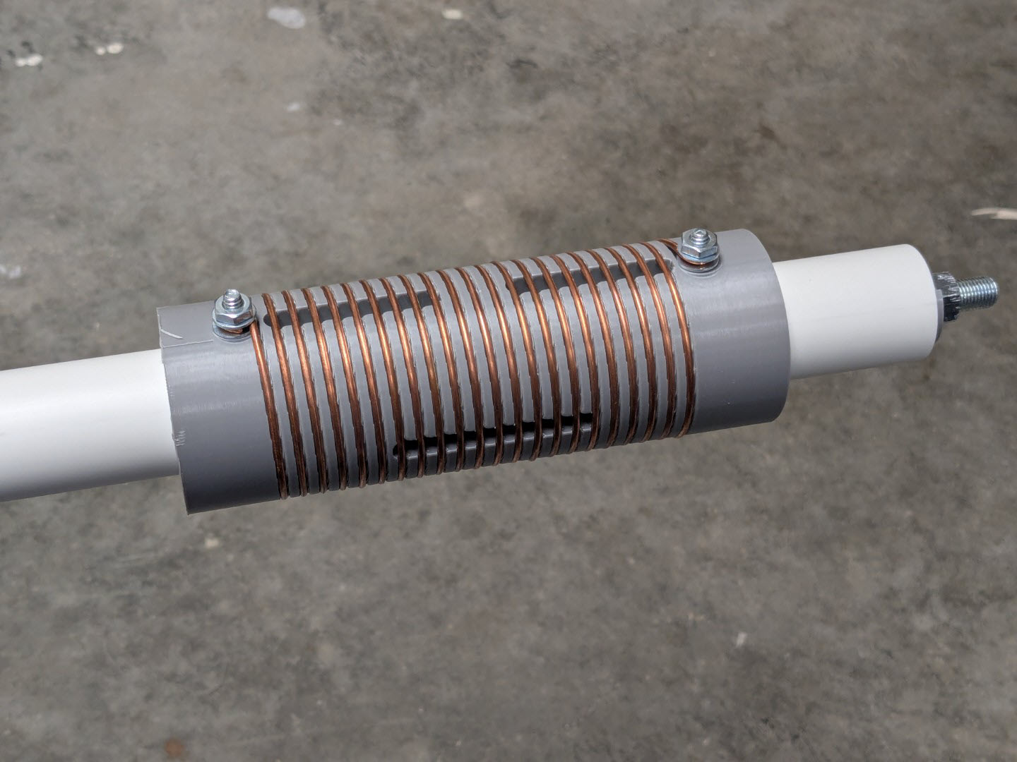
Tighten the bottom nut around the end of the coil wire and begin winding the wire around the form, using the grooves as a guide. Once the coil is completed, form a second loop of wire around the top #10 bolt and secure the nut onto the coil.
Assembling the Bottom End
The bottom end consists of the feed point and the radiating element that extends from the feed point up to the bottom of the loading coil.
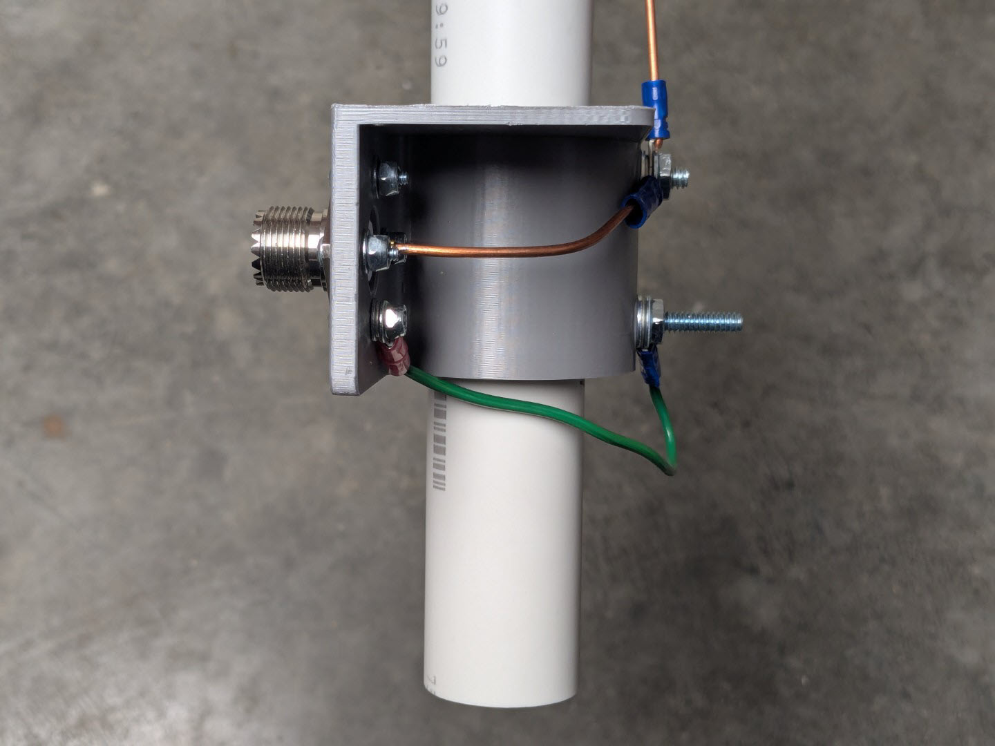
Attach the SO-239 RF connector to the feed point printed part using four 1/2" length 4-40 screws.
You will need two scraps pieces of wire to connect the SO-239 to the bolts on the back side of the feed point. Each wire should be about 4" long. On one wire, crimp a 4-40 terminal onto one end, and a #10 terminal onto the other.
On the second wire, you will crimp a #10 terminal onto one end, and solder the opposite end into the center conductor on the SO-239.
The feed point form is designed to be covered on the top side of the feed point, to help shed water away from the coax connector.
Measuring from the bottom of the PVC pipe, measure up 3.25" and drill a 3/16" hole that is lined up with the holes in the top of the PVC. It's not critical for it to be exactly in line, but should be close.
Slip the feed point onto the PVC pipe up from the bottom and just as you did before with the coil form, use the feed point bracket as a guide to drill out all four holes. Note that the shelf on the feed point is designed to be on the top side of the feed point to shed water away from the coax connector.
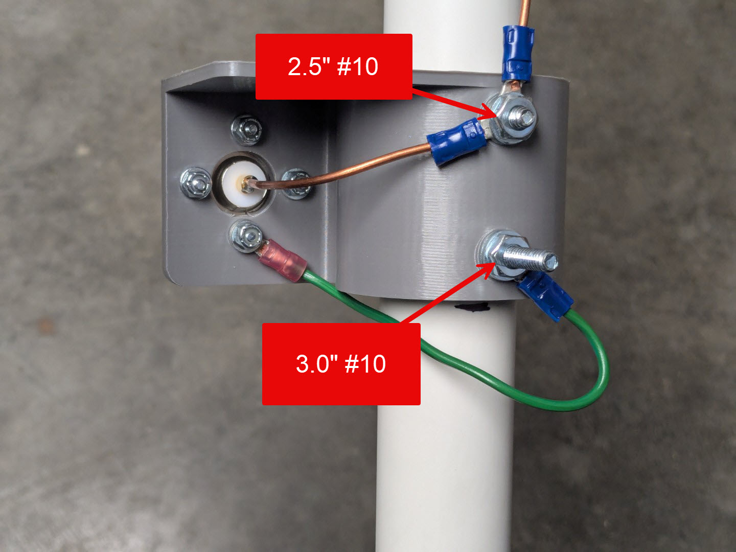
The nuts on the bottom bolts should go the same direction from the bolts used on the coil form above. For the top hole in the feed point, I use the standard 2.5" #10 bolt. For the bottom bolt, I use a 3.0" #10 bolt, which gives extra surface area to attach the radials.
Attach the short hookup wires to the center conductor and chassis side of the coax connector, and extend them around the back side of the connector and attach to the two new bolts.
The final step on the bottom half is to use a left-over piece of the 12ga wire used on the coil form to connect the top (center conductor) bolt at the feed point, to the bottom bolt of the coil form. I recommend using #10 crimp connectors, however it is important to not only crimp, but also solder these connectors as solid wire does not tend to crimp securely (ask me how I know).
Assembling the Tripod
If you are using the tripod base, cut 3 identical lengths of 3/4” conduit. I used 29” for my legs.
Drill a 1/16" hole into one side of the conduit, 1/2” from the bottom of the pipe.
Install the feet onto one edge of the conduit legs, and using a 4-40 machine screw, screw the feet to the bottom side of the legs. Note that the 4-40 screws are relatively fragile so go slowly, and wallow out the hole slightly with a drill if it starts to become tight.
Insert the legs into the base of the tripod mount. I've chosen not to include any form of attachment of the legs to the base, instead opting for a simple friction-fit. If the legs are too loose in the base, you could wrap the top of the legs with a few windings of electrical tape to make the more snug.
Once the tripod is assembled, you can insert the PVC base into the top hole of the base, and you're nearly complete.
Putting it Together
The antenna is almost complete at this point, and we just need to finish up the jumper wire at the top of the coil.
Before installing the jumper, slip the guy line mount, and guy line collar over the top of the PVC pile. The guy line mount should be free to rotate, and drill a 1/16" hole through the collar, and secure it to the top using a 1/2" 4-40 machine screw.
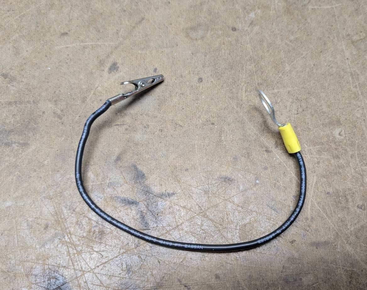
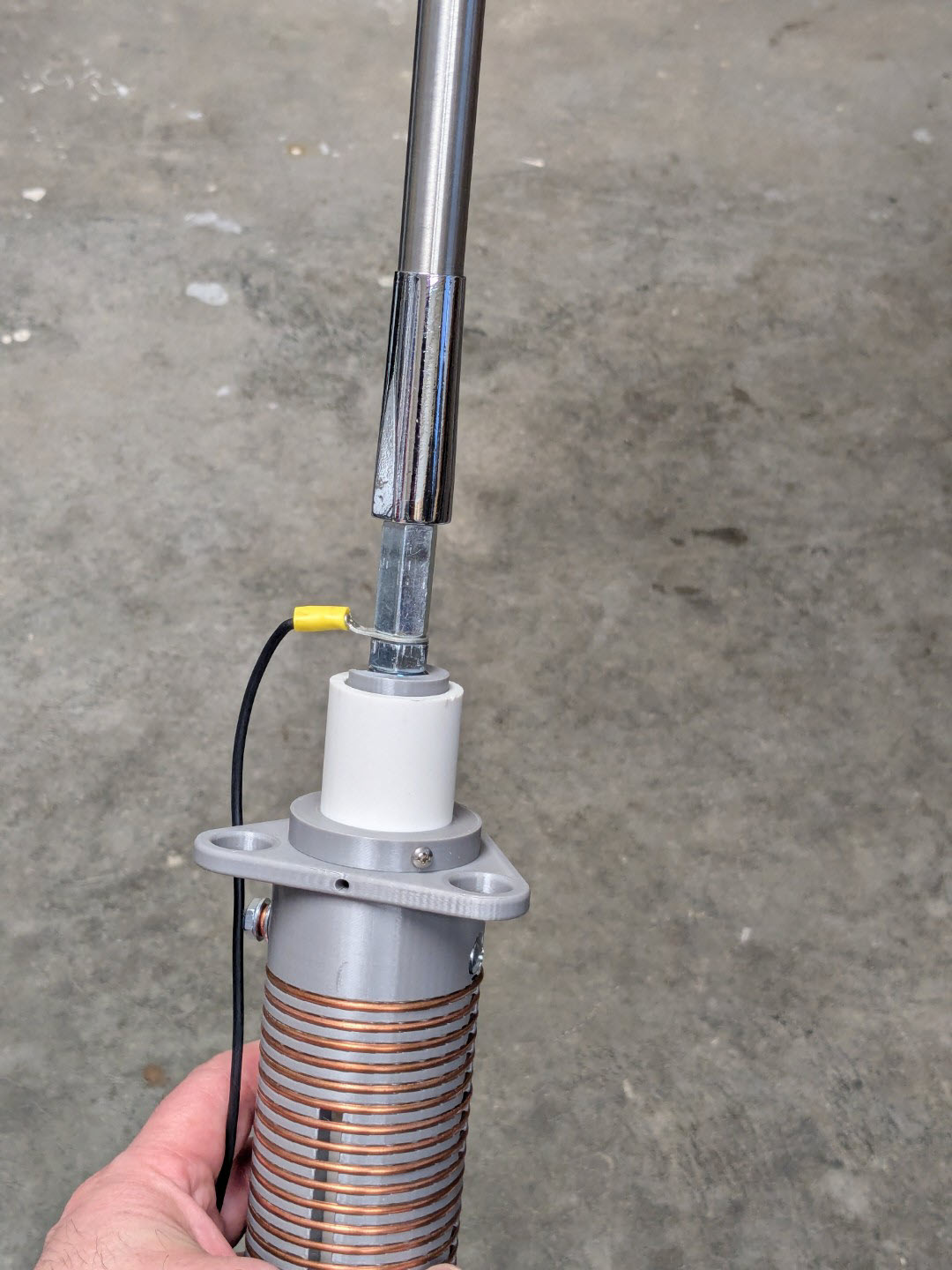
I used a quality silicon wire from Digikey for my coil jumper. I cut it to 8" long and crimp/soldered an aligator clip connector to the free end, and a 3/8" crimp terminal to the top end. The jumper should be long enough that it extends from the bolt on the carrier, all the way down to the bottom loading coil bolt, which effectivly bypasses the coil (for use on the upper bands).
Put a large 3/8" coupler on the top of the bolt in the carier to create a female connection for the telecoping whip. Insert the crimped jumper wire under that coupler and carefully tighten the coupler down. The plastic carrier is probably the weakest component in the system, and the plastic can strip out if you over-tighten the bolt or the whip.
You can now thread in the telecoping whip and the antenna is ready for operation.
Resources
Related Articles

2x6 Antenna Relay Controller

W0ZC Contact Statistics

POTA Go Kit

Pan Adapter for TS-590SG