MFJ Peak Reading Modification
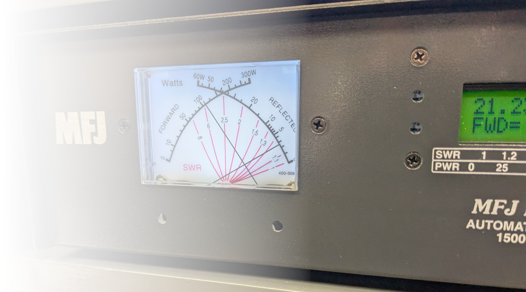
The MFJ dual-needle SWR meters, such as the one included in the MFJ-998 legal limit automatic tuner are reliable little meters for watching the power and SWR status of your transmitter. Their response times leave a little to be desired however, but with this simple modification, the meter can be a modified to show the RF peaks with adjustable dwell time.
Circuit Design
The circuit consists of a pair of 3-stage operational amplifiers. The configuration is set up as a buffer amplifier connected to a sample-and-hold circuit, which is then linked to another output buffer amplifier which is fed out to the meters.
The amplifiers are based on the quad op-amp LM324 circuits and aren't particularly sensitive to noise or performance limitations. Signal is fed in from the four-pin connector J2 and splits into separate U2 and U3 op-amps for the corresponding Forward and Reflected signal paths.
The first op-amp is wired as a buffer amplifier, which is then fed into a sample-and-hold circuit consisting of three diodes and a 2.2uF holding capacitor. There is a pair of 1M potentiometers that set the decay period of the held signal.
The final stage is another buffer amplifer, fed through a 5k potentiometer which is used to calibrate the needle movement.
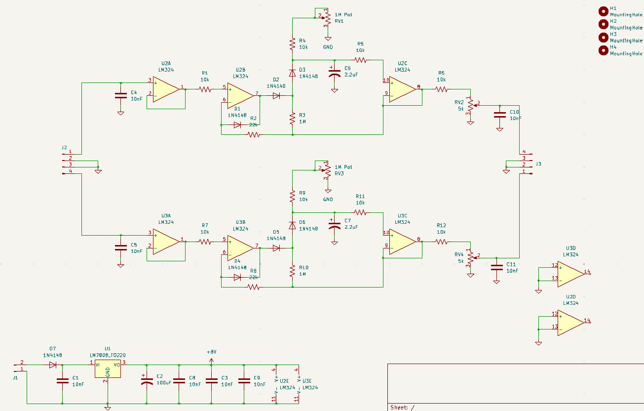
An 8V linear regulator finishes out the circuit. Power is derived from the 12V MFJ tuner supply and fed into connector J1. The current draw of this amplifier circuit is minimal, and can be tapped off of the meter's backlighting circuit.
PCB Construction
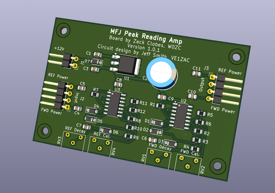
Nearly all of the components on the PCB circuit board are surface mount. The resistors and capacitors are 0805 sized devices, which are relatively easy to hand place and solder. While this may not be the best first surface mount project, it could be a good second project.
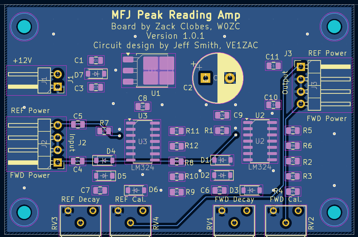
The GitHub Repo contains all of the KiCad files, including a set of Gerber files ready to be shipped to the board house of your choice. The board is double-sided but otherwise unremarkable from a processing standpoint.
Installation
Installation procedures may differ depending on the tuner model. The 12V power supply can be obtained from the meter backlighting voltage, which is supplied to the J1 connector.
Connect the forward and reflected signals that come from original SWR bridge/amplifier circuits provided from the manufacturer. The forward and reverse meter signals feed into the J2 connector, with the middle two pins serving as grounds. If your leads are kept short, you may be able to leave those grounds disconnected and simply leverage the ground being provided into the J1 power connector.
The output signals are passed out through the J3 connector on the opposite side of the board. Again, the middle two pins are connected to ground and can be used to provide a return path to each of the forward and reverse needle movements.
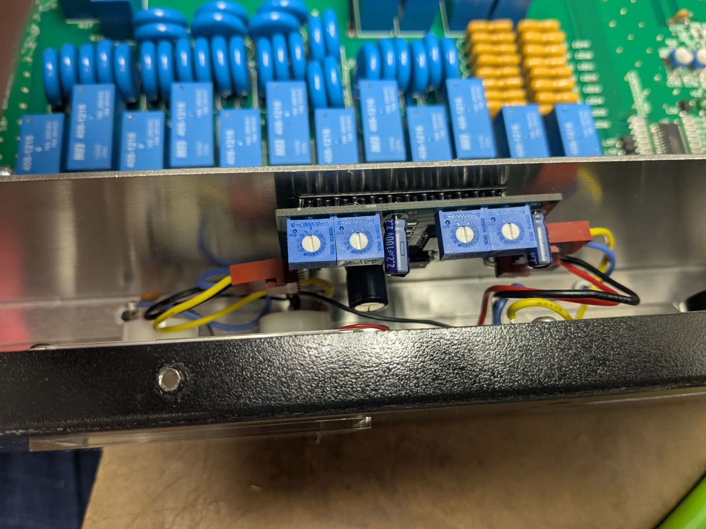
Most tuners should have ample space to install this PCB. In this photo, I attached the PCB to the side of an aluminum bulkhead immediately behind the meter. Be sure to keep the four adjustment potentiometers in a position where they can be easily adjusted after installation. Also, keep the wire length as short as possible between the output from the SWR bridge and this PCB.
Calibration
Be careful while working with live RF voltages, especially as you approach power levels exceeding 25 watts. Keep hands and tools away from the tuning coils and capacitors, as well as any RF connector inside of the tuner.
Before applying power to the circuit, adjust the two decay potentiometers to their middle setting with a small screwdriver. Turn the Calibrate potentiometers fully counterclockwise to begin with.
Apply sufficient RF power to the tuner so that it moves the needle to at least half-scale on the meter face. Start with the forward power, and adjust the Calibrate pot clockwise until the forward-reading needle reads the correct output wattage.
In the MFJ-998 for instance, you can use the built-in LCD display to know what the output wattage should be, but if you are using a different meter, you may need to use an external wattmeter wired in series from the output of the tuner, before it is passed through to the dummy load or antenna.
The reflected power is a little bit trickier, and you may need to artificially introduce some reflected power by tweaking the tuner or transmitting on a non-resonant part of your antenna system. Once you have an output power being sent, adjust the Reflected Calibrate pot clockwise until the needle reads the correct wattage.
Credits
The circuit was originally designed by Jeff Smith, VE1ZAC and was published on his website, VE1ZAC.com. It was adapted and published here with his permission.
Related Articles

2x6 Antenna Relay Controller

W0ZC Contact Statistics

Tower Installation and Budgeting

Pan Adapter for TS-590SG