2x6 Antenna Relay Controller

In a quest to enable remote operations for my home station, being able to remotely switch the antenna system seemed like the second need, after the radio itself. My needs were modest with only three antennas currently in the air, however inside the shack things got a little more complicated. I wanted to be able to switch between my radio, and any number of alternate radio devices such as SDRs, workbench radios, and other.
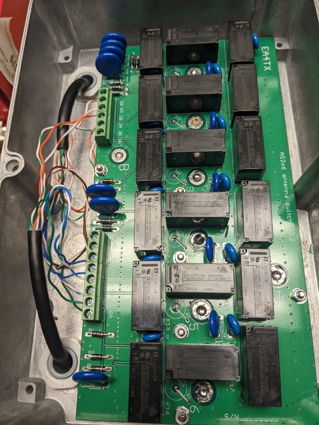
As stated, my desire to have multiple inputs inside of the shack narrowed the search dramatically for the coax relays. I briefly considered engineering my own relay boards, however I decided against it as mechanically it’s not a simple task and risk of a catastrophic failure easily outweighed any potential cost savings. After reviewing my options, I settled on EA4TX’s 2x6 relay box which handled my antenna complexities for the foreseeable future, while giving two radio outputs.
At the time of purchase, EA4TX was out of stock on any sort of Internet-enabled switch controllers, so I opted to roll my own.
Circuit Design
The external User Interface of the Antenna Controller is designed around three SparkFun modules:
- ESP-WROOM Thing Plus C
- A backlit Rotary Encoder
- A backlit 2-line LCD panel
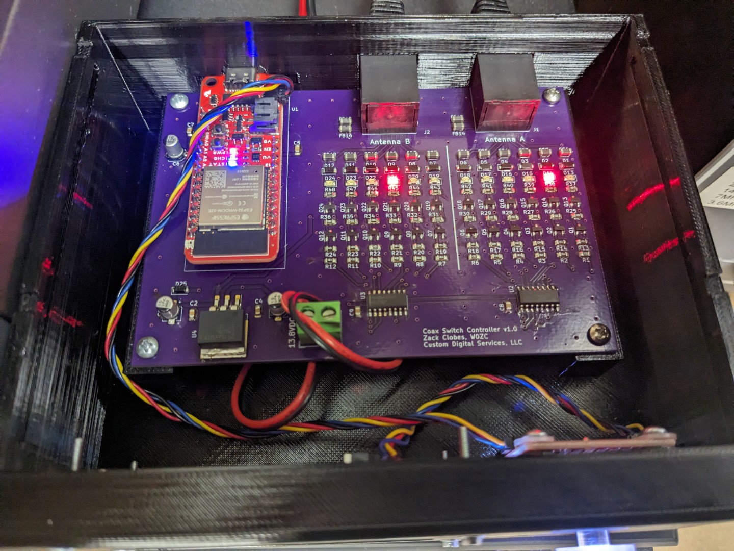
These modules which all incorporate Sparkfun’s Qwiic I2C interface made building a proof of concept quick. The hard part was that the EA4TX relay boxes require +12V high-side switching, which means that there is a single ground connection for all of the relays, and +12V has to be selectively applied to relay in question. This meant that a simple 2N2222 low-side switch which is a common control circuit in microcontrollers wouldn’t suffice.
The second complicating factor to the design is that the ESP-32 chips don’t have enough I/O lines available to them to drive all 12 relays, let alone any other control such as the I2C interface. I utilized a pair of 74HC238 multiplexers to decide the 3 binary I/O lines one-of-eight digital lines. This choice had the inadvertent advantage that it was physically impossible to accidentally connect one radio to multiple antennas.
From the 74HC238 multiplexers, 14 identical high-side driver circuits are laid out to convert the 3.3V digital logic into +12V high current drivers, suitable for enabling the relays.
The LCD display and encoder knob both connect via the Qwiic plug that is native to the ESP-WROOM Thing Plus C microcontroller, so no additional circuitry is required there. The firmware on the ESP takes care of all of the UI interfacing, as well as providing a web-interface to the controller that is accessible from the local LAN.

Firmware
The firmware for the ESP-WROOM device was developed inside of the Arduino IDE, leveraging the libraries provided by SparkFun for the LCD and knob. The GitHub project has its own documentation for downloading and loading the firmware, although I will point out that the HTTP webserver that is used depends on access to a RegEx (regular expressions) library that is disabled by default. There are instructions in the code and on the README.md file on how to enable that. If you miss this step, the code will compile however the webserver will throw a lot of 404 file-not-found errors and functionality will be limited.
There is a config.h.template that needs to be renamed to config.h, and the appropriate Wi-Fi connection information should be configured. I use a static IP address scheme on my installation so that it is consistently available on my LAN network.
Hardware
I designed the PCB in KiCad and the source files can be found inside the GitHub repository. The smallest parts are 0805 resistors and capacitors, so they should be adequately large to hand assemble if you so choose.
I’ve exported a Bill of Materials, which are all available from Digikey and SparkFun at the time of design. However, the ESP-WROOM module seemed like it was being phased out by SparkFun and I don’t know how much longer it will be available. Their website states that the WRL-20168 is the current part number, but I have not verified its pinouts or physical form factor.
I 3D printed a case for board to sit in, including a friction-fit top lid that provide easy access to the internals for troubleshooting.
Usage
Once the device is assembled and the firmware is loaded, operation is simple. Press the main tuning knob to select which radio to select an antenna for, and rotate the knob to select the antenna. The Controller will prevent one antenna from being couple to both radio simultaneously.
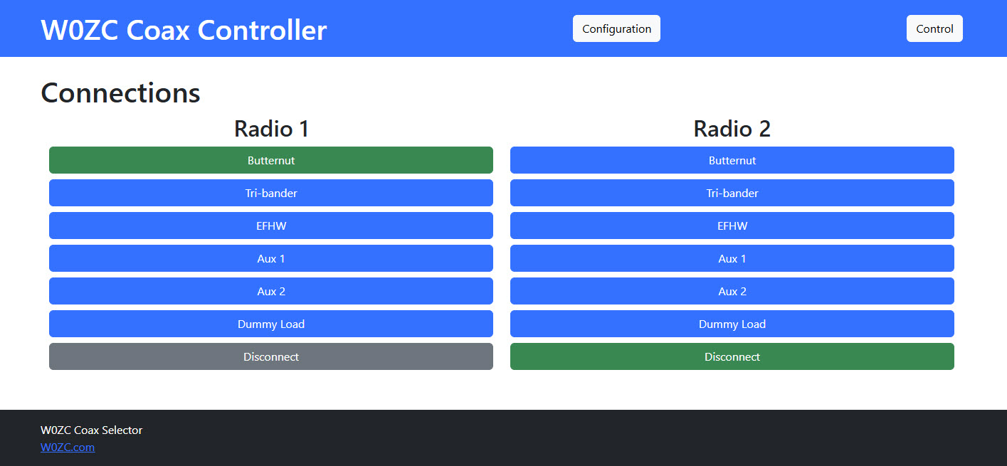
The webserver can be accessed through a browser on port 80 HTTP at the address that was configured in the config.h file above when you loaded the firmware. Type that address into a webbrowser that is on the same network as the Controller, and you should be presented with a screen showing the current status of the antennas.
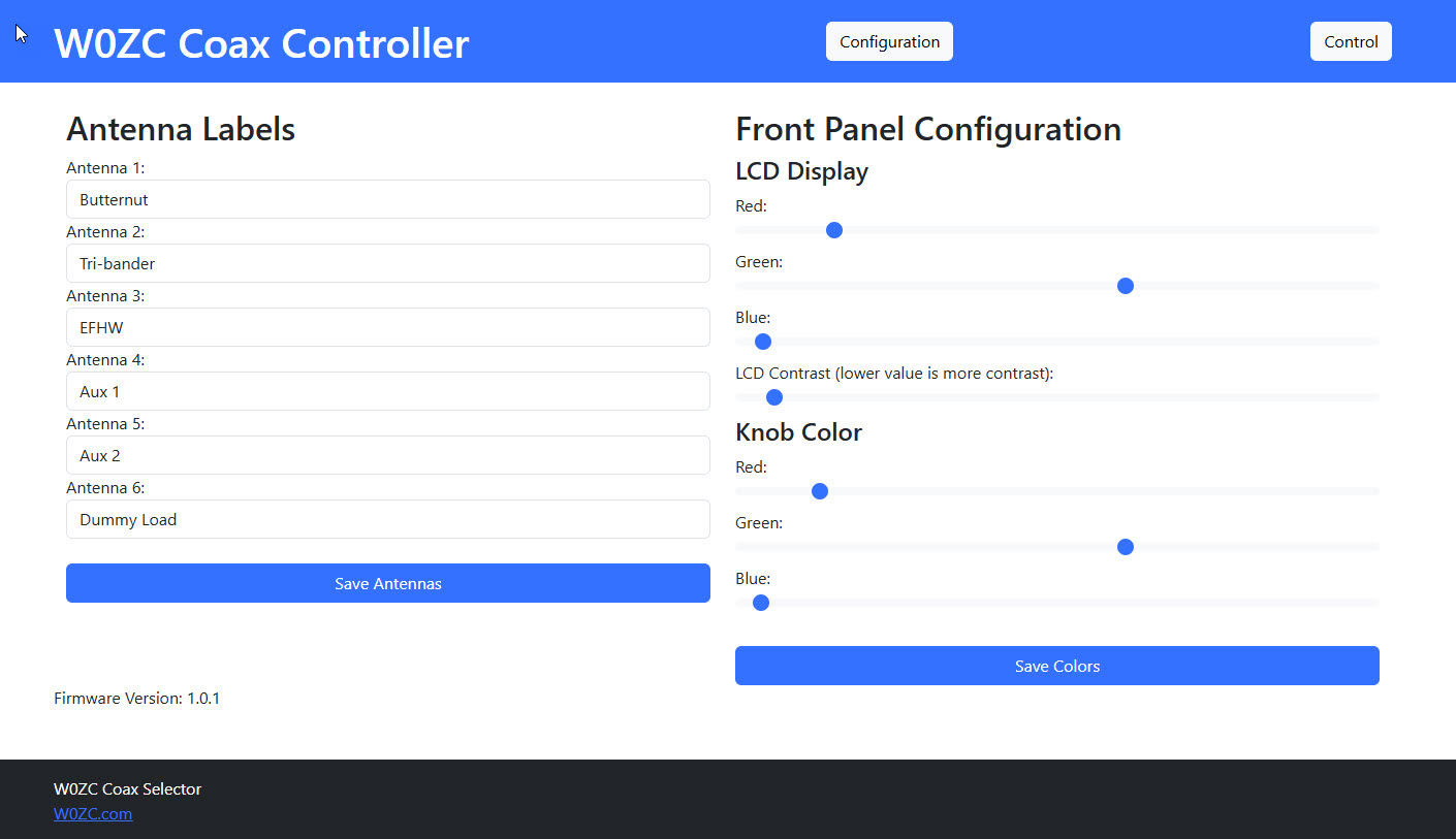
There is a Configuration link in the upper right corner to adjust configurations of the Control. This is where the individual Antennas can be labeled with appropriate names.
Powering down the Controller will automatically shunt all of the antenna inputs to ground to help reduce the risk of static build-up. At power on, the default antennas configured in the Controller will again be re-connected.
Node Red
I do have a Node Red flow configured to interface with the Coax Controller, and will be covering that in more detail at a later time
Conclusion
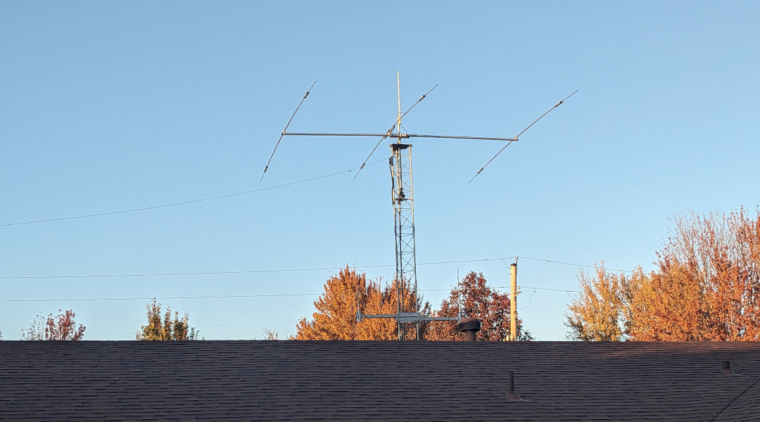
The Antenna Switch has been in operation since March of 2024, and it's been working flawlessly. I have plenty of isolation between the channels, even when I'm operating a 500W linear on one of the transmitters. I am mindful to keep the antennas that are selected physically isolated (two antennas terminate to the top of the tower, and one is about 50' away in the yard at ground level).
Parts List
- Coax Switch
- Bill of Materials
- Ethernet Cables (2x)
Related Articles


